Home > Customer Projects > Sailboat Transom Repair
Subject: Sailboat Transom Repair
Date: March 2011
Note: all images can be seen in larger versions by clicking on them.
Home > Customer Projects > Sailboat Transom Repair
Date: March 2011
Note: all images can be seen in larger versions by clicking on them.
This is a picture profile of a transom repair on a centerboard sailboat. Our compliments go to the family that made this repair, both for the quality of their procedures and the detailed pictures which make it possible for us to pass this information along to you. What prompted the repair procedure was the owner’s observation that the fiberglass was delaminating from the wood core, and cracks in the fiberglass. A little additional digging revealed that the wood core was compromised. — Doc
Pics 1 & 2: This is the boat, outside and inside, before the repair began.
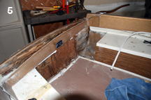
Pic 5: With the foam removed, more transom wood is exposed, and the inside laminate of the hull. This section of the seating on both sides will remain removed, since it was not an area where anyone ever sat.
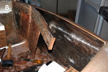
Pic 8: The main piece of transom wood came out in one piece, but a thin veneer of plywood remained attached to the outer fiberglss skin.
Pics 9 & 10: Inside views after the main part of the wood core has been removed, leaving only the veneer attached to the transom fiberglass.
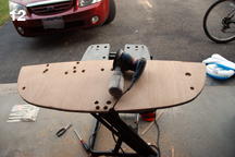
Pic 12: Holes were drilled in the new wood so that all thru-hull penetrations would be through epoxy and not through wood. Our customer reported that the challenge was keeping track of these holes through the fiberglassing part of the repair.
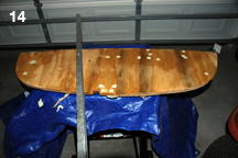
Pic 14: Both sides of the new transom were heavily treated with CPES*. Holes were filled with Layup & Laminating Resin* and West System 406 Colloidal Silica. Duct tape was placed under the holes and peeled off after the resin cured.
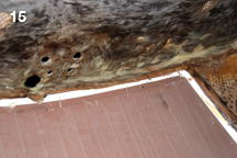
Pic 15: Voids and pocks are filled with L&L resin* and silica filler before installing the new transom piece.
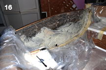
Pic 16: A heavy coat of L&L resin* and silica (as a thickener to hold the resin in place on vertical surface and to help fill the voids) is applied. A heavy coat of L&L* (without silica) filler was also applied to the transom piece to make sure there would be no starving of the bond.
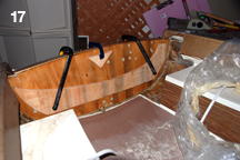
Pic 17: The new transom piece being bonded in place using L&L resin*. One needs to be careful not to permanently bond the bracing piece to the transom. Polyethylene plastic sheeting should be used wherever feasible to prevent bonding.
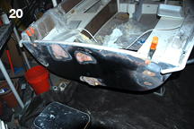
Pic 20: The outer skin had issues, including dents on each side where there were structural through-bolts. The bolts were removed, the dents filled, and then additional glass added to the outer shell for support.
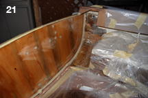
Pic 21: A very heavy filet of L&L resin* and 406 silica filler was applied all along the border of the transom and hull to increase the strength of the corner and to provide a smooth surface for the new fiberglass.
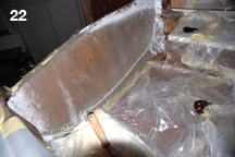
Pic 22: Before installing the fiberglass sheet shown here, two four inch strips of fiberglass (one over the other) were laminated over the filets shown in the prior picture. L&L resin* was used for all of this fiberglassing, and our customer commented that it was great resin because of its long work time and gradual set up.
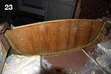
Pic 23: Two additional layers of fiberglass were installed over the transom. Note that the glass cloth virtually disappears after the L&L Resin* is applied.
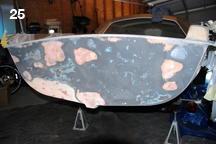
Pic 25: The outer skin was filled and smoothed, using L&L resin* thickened with filler where appropriate.
* These products are unavailable, we are selling comparable products that will perform these same tasks. Feel free to contact us if you need assistance with which products to use.
Contact us by phone 206-364-2155 or e-mail (send us your pictures) at drrot@rotdoctor.com and we will gladly answer questions about our products or how to apply them. With 20+ years of experience and many more in the boating and construction industries, not much surprises us. We are here to help our customers solve their issues. Let us help you to not have any surprises in your repair project.
Our business hours are 6:30 AM to 5:30 PM Pacific Time, Monday–Friday.
Tech support is available over weekends and holidays 8:30 AM to 5:30 PM Pacific Time.
The Rot Doctor, Inc.
P.O. Box 30612, Seattle, WA 98113
Voice: 206.364.2155
Fax: 206.364.4744
E-mail: drrot@rotdoctor.com
The Rot Doctor, Inc. ©1997–2021. All rights reserved.