Home > Customer Projects > Stacked Plywood Strips Transom Repair

Subject: Stacked Plywood Strips Transom Repair
Date: August 2007
Note: The following is a representation of our customers 9 page PDF in a web friendly version.
Home > Customer Projects > Stacked Plywood Strips Transom Repair
Date: August 2007
Note: The following is a representation of our customers 9 page PDF in a web friendly version.
Editors Note: A customer sent us an excellent, detailed description and pictures of an extraordinary transom repair of his 1977 19′ SeaRay SRV197 using our products. We would like to share this 9 page story with you in the form of a PDF (as the customer shared it with us). If you do not have Adobe Reader, go to Adobe’s website and download it (for free).
This repair is time consuming, as is the drying time for both the wet wood and the chemicals. This job took me 180 hours over a 4-month period. This included the removal and reinstallation of the interior in the rear and a thorough cleaning of the entire boat once the repair was completed. The boat is a 1977 19′ SeaRay SRV197.
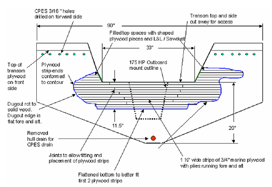
During the removal of my old motor for installation of a new motor, the dealer informed me that the transom was weak. Somewhat discouraged I knew I was in for a transom repair before the new motor could be installed. After considerable research on transom repairs, I decided to do the job myself to insure it was done properly and strong. I conceived of this stacked plywood strips method after carefully reviewing other methods. (See the Transom Repair Drawing at the end of this article.)
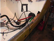
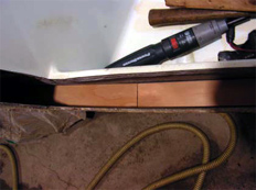
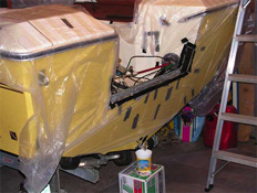
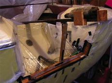
I began by cutting the transom top and part of sides to provide access to the wet and rotted wood.
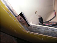
Other side was cut similarly
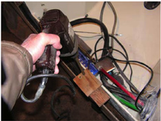
I dug out most of the rotted wood with a hook shaped tool and a 1¼ inch spade bit on a long extension. I also used a 1½ inch spade bit with a jig to limit the depth of the drilling and to produce a flat and square bottom of the dugout area. This was done to provide a level starting point for the first layer of the plywood strips.
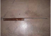
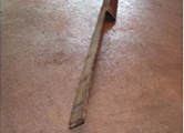
I squared the dugout sides using a home made ‘chisel’ made by cutting off part of one side of a piece of 2 inch X 2 inch angle iron. I sharpened the end of the blade portion by grinding to make a cutting edge. It was about 3 feet long and I was able to use it without a hammer. That made it easy. I bent the end of the chisel slightly near the tip so I could use it along with a 1½ inch drum sander to clean the wood from the fiberglass sides of the dugout area. This worked very well.
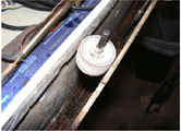
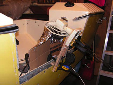
When all the rotted wood was removed, I used a hair dryer and a fan to help the transom dry out for a couple of weeks.
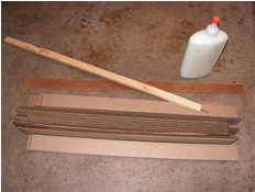
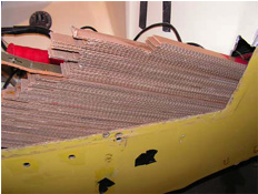
I duplicated the contour of the dugout area using many strips of cardboard laid flat and glued together along the center of each strip. The strips were cut about ½ inch narrower than the transom opening to make them easier to install and remove. I used a small piece of wood about 18 inches long with a sharpened nail in the end to “stab” the cardboard strips to slide them in the glue to ensure they reached the sides. The two halves (left and right) needed to be tied together in place so that they could be reassembled at the same width once removed. This was done to provide an accurate template of the shape of the dugout area. I used four overlapping longer strips of Masonite in place of cardboard strips placing two near the bottom and two at top to tie the two halves together. It worked, but I would use strips of ¼ inch thick plywood the next time for more stiffness. I put a screw through the two pieces of overlapped Masonite at the bottom and top to keep the right distance apart for reassembling once removed. Once the two halves were removed, I assembled them with the screws and then traced the pattern for cutting the wood strips.
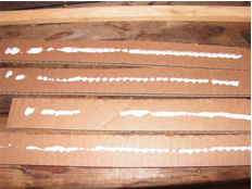
Left and right halves temporarily tied together with a screw for reassembly once removed.
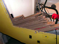
Ready to remove the halves
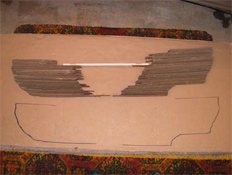
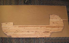
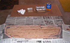
Traced outline was used to fit the plywood strips
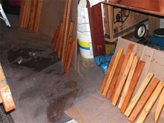
I used fir marine plywood for maximum strength. I cut the plywood into 1½ inch wide strips so they would just fit in the transom opening width. I then cut them to match the contour and length of the traced shape. I made the longer strips in two pieces to allow them to be installed. I staggered the joints of the strips so that they all were near the sides of the transom opening and not in the middle where most of the bending load is. I inserted a nylon strap loop into the opening before fitting the wood strips to make it easy to remove them. It is not necessary to be totally accurate cutting the end contour of the strips, but the length is critical for maximum strength. I left as little a gap between the ends plywood strips as possible.
Staggered wood strip joint
I removed the strips one layer at a time by pulling on the nylon strap. As I remove them, I marked each strip with information that would allow me to replace them in the right order. A pencil is suggested for marking the wood as it will not run or disappear when the CPES* is applied.
All wood strips cut
I cleaned the edges of all the large boltholes in the outer transom fiberglass with a rat-tail file to provide good bonding of the CPES* and L&L epoxy*. I also filed all the edges of the fiberglass transom cutout section for a good bonding with CPES* and Fill-It*. I also cleaned all screw holes in the transom with a small triangular file in a drill. A drill bit smaller than the hole could be use too. I used the Injection Kit to put CPES* in the screw holes that went into the original transom wood to seal them. I would later fill them with an L&L*/Sawdust mixture to be redrilled for mounting the swim platform support screws, depth sounder and hull drain.
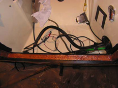
I carefully covered all small holes and bolt holes on the outside of the transom with electricians tape to contain the CPES* and the L&L epoxy*. I made sure the tape was not concave into the holes, to prevent the opening from being concave once the L&L* set. I also used some strong clear packaging tape on larger areas on the inside of the transom where the fiberglass broke through when removing the rotted wood. The tape was used to contain the CPES* and L&L*. Both tapes worked very well.
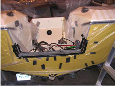
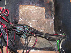
Inside breakthrough area
Drain
All the plywood strips were soaked in CPES* in a makeshift “pan” out of 4 mil plastic sheet. I placed the plywood strips on edge and sprayed on CPES* until they were saturated. In checking for complete coverage, I found that it was necessary to coat the sides of most of the plywood strips with a brush. The strips took about 2/3rds of a 2 quart unit of CPES*. The transom opening and the plywood strips were done in two separate applications. This was done so that I could devote time to each without having to rush or worry. When I coated the sides of the plywood strips, I brushed them in the makeshift pan, and in doing so I poked some small holes in the 4 mil plastic sheeting with the sharp corners of the plywood strips. My suggestion would be to cover the bottom of the makeshift pan with overlapping strips of packaging tape to seal and add resistance to puncturing. If you don’t, the CPES* will leak through and coat the surface underneath.
I had to let the CPES* in the transom and plywood strips dry for two weeks at temperatures in the 25-50 degree F range to get most of the volatiles out of the wood strips.
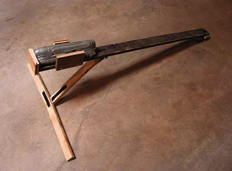
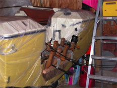
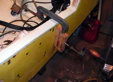
I made a device to press the plywood strips into the transom while applying the L&L epoxy*. It consisted of a weighted lever to keep the plywood strips from “floating” in the L&L epoxy* and to keep the L&L epoxy* thickness between the plywood strips consistent. The photo shows a slight angle on the contact arms so it would put the pressure on the center of the plywood strips rather than the edges, and also to minimize the amount of epoxy mess on the device.
I was able to apply the L&L* into the transom dugout before each strip was installed with an extension attached to a disposable 1″ brush. I hand painted the sides, ends, and the bottom of each strip with L&L* before installing each one. I pounded each strip with a piece of wood or pried the strips down in the wings of the transom opening to seat in the L&L*. I installed several layers then placed the device to gently squeeze the excess L&L* from between the strips. I left it in place with the weight on it when I finished the last full length of strips in the transom.
I installed the plywood strips on a 50-degree day and had plenty of time to work with the L&L epoxy*. The low temperature made the L&L* plenty thick and sawdust was not needed. When most all the strips were installed, I ran out of L&L* just short of the top of the transom. This was actually a good thing in that the height of the wood strips without the L&L epoxy* was shorter than the height when L&L* was added. I had neglected to account for the thickness of the L&L* in between the strips. I discovered that the L&L* amounted to about ½ inch per 16 wood strips. While waiting for more L&L*, I adjusted the rest of the previously cut strips by reducing the thickness of one long section to make the rest fit. This plywood strips method of repair makes it possible to stop in the middle of the installation, as I needed to do.
I clamped the transom together with made-up stiff supports to close the slight rearward bow in the outer transom fiberglass and let it set up one week. I did not clamp the plywood strips in the vertical direction, because that would squeeze too much of the L&L epoxy* from between the strips in the high load area. When I finished the transom after the new L&L* arrived, all the rest of the strips fit perfectly. At this point I had put 85.5 hours into the repair.
One note on the L&L*. This is sticky stuff and drips easily. Mask (with plastic and tape) all the areas you want to protect. For sure L&L* will get on it if you don’t. Set up separate areas for mixing, applying, and clean up. Have everything in place before you start. Many rags and plastic on the floor are necessary. Plenty of lacquer thinner is needed for clean up.
After the all the plywood strips were installed and L&L* set up completely, I prepared to fill the top of the opening with Fill-It* by attaching a straight piece of wood. I first covered the piece of wood with electricians tape to prevent the Fill-It* from sticking to it. I then taped it to the rear edge of the transom opening to provide straight and level edge for screeding the Fill-It* to form a square edged transom top. (Note: If you plan to finish the transom opening with right angle anodized aluminum as I did, the transom top must be square to the transom angle.) I then added a coating of L&L* mixed with sawdust to roughen the area for a good bond with the Fill-It*. I sanded and cleaned the previously cut out pieces of the fiberglass transom top and sides and painted both sides with a coat of CPES* and let it set up for a day. I put in a layer of Fill-It*, coated one side of the cut out pieces of the transom with Fill-It*, and pressed them into the first layer of Fill-It*. I then added more Fill-It* and screeded off the excess Fill-It* to form a nice looking transom top. Using the original transom top pieces saved on the amount of Fill-It* used. When the Fill-It* hardened, I removed the straight edge and finished the opening by filing and sanding the edges. This worked very well.
I drilled the motor well drain holes for installing new drain fittings. I then coated the inside of the drilled holes with the two coats CPES*. Once dry I installed the new drains using Sonolastic ULTRA*. Paint thinner worked fine for removing the excess sealant. I used a similar procedure for reinstalling the brass hull drain fitting.
I cut 2″X2″ by 1/8″ thick anodized aluminum angle to dress up the opening. I used clear nail polish to coat the cut ends to prevent corrosion. I installed the aluminum trim pieces with only two stainless steel screws for each piece, since this is only cosmetic trim. I then sealed all the exposed edges with Sonolastic ULTRA* sealant. I used masking tape close to the aluminum edges to provide a clean and neat appearance. The Sonolastic ULTRA* is stiff, but can be made into a nice fillet radius with heavy finger pressure. I removed the masking tape after the Sonolastic ULTRA* set for a while. This worked very well.
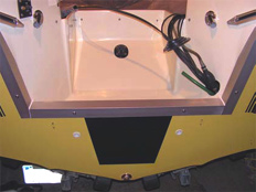
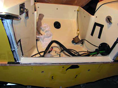
I removed the packaging tape on the inside of the transom and used Fill-It* to blend in the areas where there was uneven match up with the original inside fiberglass. I then placed kitchen plastic wrap over the uncured Fill-It* and ‘smoothed’ it with a rag. This provided a wrinkled surface texture that very closely matched the random texture of the original fiberglass sprayed on coating. Once set up, I removed the plastic wrap and smoothed the area to remove any nubs and painted the areas to match the original semi gloss black paint. This worked very well.
I coated the motor mounting area on the outside of the transom with a black polyurethane product. I applied it with a roller to provide some texture to hide some very slight transom surface irregularities from previous mounting holes. This worked very well.
After a little buffing of the remainder of the transom area and motor well with fiberglass rubbing compound, the transom repair was done. When the new motor was install, I had the dealer coat the inside of the four drilled mounting holes with two coats CPES* to seal the holes. I also had them install a home-made aluminum motor well transom plate I painted black to match the new motor. I also had them install 3 inch square 1/8 inch thick stainless steel plates and washers on the inside of the transom. All these and the mounting bolts were sealed with Sonolastic ULTRA* so that water could not enter my “new transom”. The rear interior seats and motor well trim were installed after the motor was installed.
| Product Used | Amount Used |
| CPES* | 2 - 2 qt. Units |
| L&L epoxy* | 2 - 2 qt. Units |
| Fill-IT* | 1 - 2 Pint Unit |
| Sonolastic ULTRA* | 1 - 10 oz. Tube |
| Marine plywood (Fir) | 1/2 of a 4X8 foot sheet |
| Anodized Alum Angle | (1/8″ thick) 6 ft (2″X2″) |
| New motor well drains | 2 |
| Elbow grease | Lots |
Much thought went into this repair to figure out how to do it and to solve the problems along the way. Was it fun and exciting? You bet! Did it come out well? Yes, and I am very pleased. Would I do it again? Yes, but not for a long time.
Dan
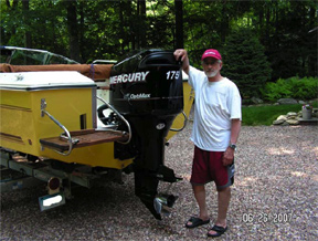
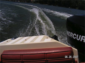
New outboard installed

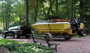
Well worth the wait
Transom Repair Drawing
* These products are unavailable, we are selling comparable products that will perform these same tasks. Feel free to contact us if you need assistance with which products to use.
Contact us by phone 206-364-2155 or e-mail (send us your pictures) at drrot@rotdoctor.com and we will gladly answer questions about our products or how to apply them. With 20+ years of experience and many more in the boating and construction industries, not much surprises us. We are here to help our customers solve their issues. Let us help you to not have any surprises in your repair project.
Our business hours are 6:30 AM to 5:30 PM Pacific Time, Monday–Friday.
Tech support is available over weekends and holidays 8:30 AM to 5:30 PM Pacific Time.
The Rot Doctor, Inc.
P.O. Box 30612, Seattle, WA 98113
Voice: 206.364.2155
Fax: 206.364.4744
E-mail: drrot@rotdoctor.com
The Rot Doctor, Inc. ©1997–2021. All rights reserved.